Operation
External Triggering Mode
To operate the stroboscope in external triggering mode:
1. Connect external trigger or sensor wires according to
connector pin designation:
1 +12V (for powering sensor)
2 Synch output signal
3 External input signal
4 0V (common)
2. Firmly plug in power cord.
3. Turn power switch on.
4. If INT lamp is on, press “SIG” until EXT lamp turns on.
5. Press “MODE” to select proper mode:
FPM Light will flash in correspondence with input signal;
the input signal will be calculated into FPM and
displayed.
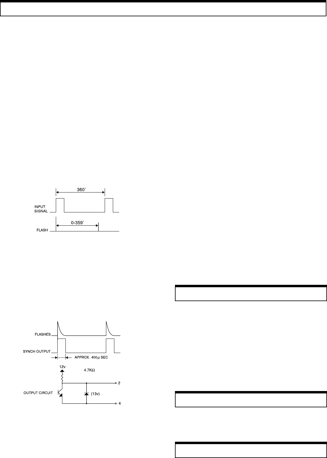
deg One cycle of input signal is 360°. A delayed angle
will be displayed from 0 up to 359°. (The delayed
angle can be changed by turning the knob setting as
previously described).
msec The above delayed angle will be displayed in msec.
NOTE: If the input signal frequency exceeds upper or lower
limits, the alarm dashes (-----) will be displayed and the strobe
will stop flashing.
NOTE: Once the internal timer has expired, the strobe will stop
flashing and the display will flash rapidly. To restart the strobe,
turn power switch off, then on, and the cycle will repeat.
Synchronous Output Signal
For triggering and controlling additional stroboscopes, the
synchronous output signal appears on pin #2 (see below).
Flash Tube Replacement
When FPM reading is displayed but unit is not flashing, flash
tube may need to be replaced:
1. Unplug line cord from power line.
2. Turn power switch off (wait a few minutes until
stroboscope is cool before proceeding).
3. Remove protective window by removing the 4 screws.
4. Use tube removing tool provided: insert tool all the way
and turn clockwise until tool locks. Pull out tube.
5. Install new flash tube using the removing tool.
6. Replace protective window.
7. Mount reflector in the center so that the reflector will not
interfere with the screw spacer on the corners.
If battery is low, “LLLLL” is displayed and display will eventually
disappear. Charge battery as follows:
1. Turn power off.
2. Insert AC adapter/charger plug into the strobe receptacle
(CAUTION: charge the unit only with the provided AC
adapter/charger).
3. B-CH lamp will be lit during battery charge; within 2 hours
the battery should be charged completely.
NOTE: The adapter/charger may be used as a power supply to
power the strobe continuously.
Battery Charge (DT-315A Only)
Battery Replacement (DT-315A Only)
The life of the built-in battery should last for approximately 300
charges. If the time period between recharges becomes
increasingly shorter, then replace battery with a new one.
FPM Display Mode
If the input signal exceeds 585Hz, the upper dashes on the digital
display will be flashing:
----- upper dashes
If the input signal is lower than 0.67Hz, the lower dashes on the
digital display will be flashing:
----- lower dashes
Deg/msec Display Mode
If the input signal exceeds 167Hz, the upper dashes on the digital
display will be flashing:
(deg) ----- upper dashes ----- (msec)
If the input signal is lower than 0.67Hz, the lower dashes on the
digital display will be flashing:
(deg) ----- lower dashes ----- (msec)
Memory
The following parameters are set at the factory:
• Decimal point: autorange
• Internal timer: continuous
• External trigger edge: L-H (Lo to Hi)
These parameters can be changed in the field to facilitate different
situations. To change any of the above parameters, follow these steps:
1. Turn power on.
2. Make sure that INT lamp is on. If not, press “SIG” until it
turns on.
3. Change the desired memory parameter:
a. To change the decimal point
Press “÷2” and “-“ at the same time for approximately
2 seconds until display alternates between —1— and
0.0. Press “+”. The display will freeze and show 0.0.
Change decimal point accordingly by pressing “+”. If
0.0 is selected the decimal point is in the autorange
mode. If 0 is selected the decimal point is eliminated
throughout the entire range.
b. To change the internal timer
Press MODE. The display will alternate between
—2— and 0; press “+”. The display will freeze to 0.
Use the setter to set timer anywhere between 1 and 120
minutes.
c. To change the trigger edge or the external mode
Press MODE. The display will alternate between
—3— and L-H. The external trigger edge is set from
the factory to occur during the positive transition of the
incoming pulse. To change it to the negative transition,
press “+”. Display will change from L-H to H-L.
4. Press “SIG” to go back to normal operation.
NOTE: the above settings can be checked quickly by performing
steps A to C as described above and then pressing “SIG”.
 (4 pages)
 Manymanuals.com
 Manymanuals.de
 Manymanuals.fr
 Manymanuals.it
 Manymanuals.pl
 Manymanuals.cz
 Manymanuals.es
 Manymanuals-pt.com
Comments to this Manuals